


Senior Editor
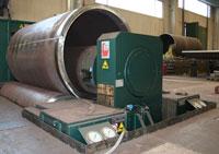
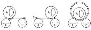
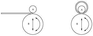
Figure 1: This three-roll, variable-geometry system has a top roll that moves up and down, with bottom rolls that move side to side.
Jeff Visser remembers the day he was thrown to the wolves. He was a newbie plate rolling operator in a job shop known in the area for its rolling expertise. He spent months shadowing experienced technicians who showed him tricks—open the rolls here to reduce pressure, shim a little there. Then he was sent to operate a machine on his own. He had no production runs. Every day he set up new jobs, overcame challenges, and learned something new.
As production manager at Avon, Mass.-based BEPeterson, he ensures his operators—especially the newbies—continually learn something new, mainly by shadowing those with more experience. Many plate rolling operators have a lot of gray hair. They won’t be working forever. And as a presenter at PlateFab: Workshop & Tours, an event organized by the Fabricators & Manufacturers Association, he hopes, at least in a small way, to spread his plate rolling knowledge to the next generation.
The editors of The FABRICATOR sat down with Visser to discuss some of that knowledge. Most of it boils down to two fundamental pillars: knowing material properties, and how pressure from a plate roll affects those properties.
The FABRICATOR: Explain some critical elements of material properties when it comes to plate rolling. What does a new operator need to know?
Visser: I’ve found that many new operators don’t know the differences between materials, be they aluminum, steel, stainless steel, or anything else. One grade of metal will roll far differently from another. For instance, aluminums can vary in strength from T0 to T6. The aluminum 50 series can be a T0 (very soft) while a 60 series can be at least a T3, and sometimes even a T6. Many new operators will roll all aluminums the same way, with the same roll pressure and locations, and then end up in a world of problems.
Steels are the same way, of course. You have your conventional A36 material, but then you can have your 516 grade, which is double the tensile strength. And then you get into abrasive-resistant (AR) plate, which looks like regular steel, but it’s an entirely different ballgame.
The FABRICATOR: Take us through the specifics. How exactly do these differences change the setup at a plate roll?
Visser: The setup obviously varies with the type of plate roll. But for the sake of this discussion, we’ll use the common initial-pinch, three-roll system (see Plate Rolling Menu sidebar). One outboard roll (the pinch roll) moves up and down, slightly forward from the fixed top roll, while the outboard roll behind it (the bending roll) moves diagonally, toward and away from the fixed top roll. The pinch roll provides the pinching pressure, while the bending roll’s position determines the forming geometry.
Plate rolls need a place to grab the material during forming. That’s why, in any plate rolling situation, you have a narrow unbent flat section on the plate’s leading and trailing edges. An operation known as prebending reduces the length of these unbent flat sections.
You perform a prebend to the plate’s leading edge, then the trailing edge, and then perform the actual rolling. In production bending with double-pinch, four-roll systems, it’s possible to prebend the leading plate edge, perform the rolling, and then the prebend (in this case it could be called the postbend) to the trailing edge. But in most common setups, prebending is performed before rolling the cylinder.
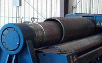
Figure 2: Most plate rolls, like this four-roll system rolling a tight cylinder, have fixed top rolls. The bottom rolls move to form the cylinder to the desired shape.
Plate rolling boils down to controlling the forming pressure. Softer materials generally require less pressure than harder materials. Say you operate an 8-foot-long, initial-pinch plate roll with a 10-inch-diameter top roll and 7-in.-diameter outboard rolls. You have two aluminum cylinders to form, each with an identical wall thickness and diameter—only the grade of aluminum changes. One is a T0 (low tensile and soft) while another is T6 (high tensile and relatively hard).
The T0’s yield strength, or break point when the material starts to form, is dramatically lower than T6’s yield. This makes the rolls’ positions drastically different, even though the materials are of identical thickness and they’re being rolled to identical cylinder diameters. Remember, the top roll is fixed. Just for illustration purposes, divide the bottom roll locations into segments 1 to 10—1 being the most open and lowest pressure, 10 being the tightest with the most rolling pressure. T0 aluminum might require a bending roll location of 3, while T6 aluminum might require the bending roll to move all the way up to 6. In a real application, the bottom roll positions may differ as much as 4 in., and this is just between two grades of aluminum.
For new operators, this can be very difficult to comprehend. It’s all about understanding the material properties. T0 aluminum will emerge from the plate roll with limited springback. Meanwhile, the T6 material may be fed into a roll configuration that looks as if it will produce a cylinder that’s only 12 in. in diameter. But that material can spring back to form a 24-in.-diameter cylinder.
The same thinking goes when rolling overlaps in thin material. A cylinder of thin T6 aluminum may require that the machine roll an overlapped seam (that is, the leading and trailing edges overlap each other) between 6 and 8 in. deep, far too much for most welding situations. But when you release the rolling pressure, it springs back to an appropriately narrow overlap joint.
The FABRICATOR: How does plate rolling compare with press brake operation?
Visser: It depends on the kind of plate roll you have. A variable-geometry plate roll has a top roll that moves up and down, like a press brake punch, and outboard rolls that move back and forth, like an adjustable-width V die (see Figure 1).
But the more common fixed-top-roll variety does operate differently (see Figure 2). On a press brake, generally speaking, the bend occurs at the same location with every stroke, directly below the punch tip. That’s not the case with a plate roll. Every time you raise or lower the bending roll, the position of the moment of bend changes. On an initial pinch roll, the more you raise the lower rolls, the more pressure you add, and the closer the moment of bend gets to the initial pinch rolls (see sidebar illustration). The less pressure the pinch roll exerts and the lower the bending roll is, the farther away the moment of bend is from the initial pinch point.
Springback is different too. When you’re air forming on a press brake, you have three points of contact: the two die shoulders and the punch tip. You have an isolated forming zone at the bend line. In plate rolling you’re essentially forming hundreds of bend lines, one instantaneously after the next. You don’t have an isolated zone for springback. Forming variation between material grades, and even different lots or heats of the same material, becomes greater.
In thin-gauge applications, you also have to worry about how the rolled cylinder will behave as it climbs up and over the centerline of the roll. Gravity works. Thick plate has the structural mass to maintain its shape throughout rolling. Thin sheet, on the other hand, may bow under its own weight. This in turn actually can change the point of bend, forcing it slightly away from the pinch rolls and toward your bending roll. You need to know how to accommodate for this, moving the bending roll slightly upward to maintain as constant a forming radius as you can. For tight-tolerance work, you may need additional supports overhead and even to the sides to guide the metal throughout the rolling process (see Figure 3).
The FABRICATOR: Explain the hourglass and barreling effects in rolling. How do they occur, and how can they be prevented?
Figure 3: This precision rolling operation requires sheet support on the side and overhead.
Visser: The goal is to achieve a parallel line of pressure. This is easier said than done, though, when you consider the nature of the plate roll. Like a press brake, a plate roll is more rigid near the ends—near the rigid machine frame—than it is in the center. That’s why forming pressure can cause the rolls to deflect more in the middle. So like press brakes, plate rolls employ crowning. In most common applications, rolls have slightly thicker diameters in the middle.
A plate roll may have a level of crowning that will accommodate the majority of workpieces it will process to ensure the operation achieves that imaginary parallel line of pressure across the rolls. At least that’s the ideal situation. Of course, plate rolling shops, especially job shops, thrive on offering diverse rolling capabilities. Plenty of jobs may fall outside the norm, and operators need to know how to compensate both for insufficient and excessive crowning.
Insufficient crowning causes a barreling effect, with the ends of the cylinder rolled to a tighter diameter than the center. Excessive crowning produces the opposite: a cylinder with an hourglass shape.
To correct this, you can either increase pinch pressure or shim. To know which solution to use and to what extent, you first need to know your machine’s rolling capacity and the behavior of the metal you’re rolling. Increasing pinch pressure can work, but you must ensure that the material—considering the grade, thickness, workpiece shape, and diameter—isn’t close to the maximum forming capabilities of your machine.
Next, you need to know how the material will react to increased pinch pressure. Increasing pinch pressure works for some materials, but not others. For most stainless steels, you can add more pressure. But when you’re working with soft metals, such as softer aluminum grades, increasing pinch pressure can end up distorting the material. I call it the “pie-doughing” effect. Like thinning out a piece of pie crust, soft material can thin and distort under excess pinch pressure.
Finally, you can move forward with a plan to compensate for incorrect crowning. If your workpiece emerges and you find it has a slight barrel shape, you have two possible scenarios. Either the pinch roll position was not set correctly and too much pressure was initially applied, or there just isn’t enough crowning in the middle of the roll.
With a crowned roll, each incremental change in pressure will change deflection more in the center than on the ends. When you get a slight barrel shape, the center of the roll is deflecting downward too much. Looking head-on, you can visualize that line of roll pressure resembling a slight smile—higher on the sides, lower in the middle.
In this barreling situation, if you didn’t wrinkle the ends of the part (lucky you), try decreasing the roll pressure slightly. Ideally, you can decrease pressure to the point where the middle deflects just enough so that the roll surface is parallel with the edges. This achieves the desired result: again, that parallel line of pressure across the length of the workpiece.
However, if you have significantly insufficient roll crowning for the job, roll pressure changes may not be as effective. With insufficient crowning, a little pinch pressure reduction on the ends does reduce deflection in the middle to some extent, but not enough to eliminate the barreling effect.
If the workpiece emerges in a slight hourglass shape, you have excessive crowning for the job. If you visualize a line of pressure across the roll, this time it would look like a slight frown—higher in the center, lower on the sides. You can try increasing the roll pinch pressure—only, of course, if your machine can handle the increased tonnage. This increases the deflection in the center, pushing the center downward. The slight frown turns into a straight line of pressure across the workpiece.
If altering roll pressure doesn’t work, you need to resort to shimming. Placed in the middle, the shims themselves—which can be pieces of cardboard, plastic, or even thin-gauge sheet metal—effectively add crowning, ideally to the point where deflection in the center matches the deflection on the ends. Placed on either side of the workpiece, the shims can compensate for excessive crowning.
Exact shim placement can vary from job to job. I’ve actually seen some complicated shimming, such as a 2-ft.-wide piece of cardboard on top of a 4-ft.-wide piece, on top of a 6-ft.-wide piece, adding a larger bulge in the middle of the roll. This isn’t ideal, though. You really don’t want to go down that road too far, because it’s not what your machine was designed to do. Ideally, you need a machine with the right capacity and crowning for the job at hand.
In fact, we have a high-end plate roll with no crowning at all, simply because the rolls themselves are oversized. It’s a precision-rolling application, about ±1⁄32 in. on the circumference, and it involves extremely soft aluminum. Any crowning whatsoever would have given us that pie-doughing effect. So instead, we oversized the rolls for the application, so we effectively get no noticeable deflection, and even pressure is maintained across the rolls. That’s an unusual (not to mention pricey) solution, but it’s an available one.
The FABRICATOR: For you, what makes plate rolling unique?
Visser: Until they come up with a way to make every plate of a specific grade have exactly the same forming characteristics, regardless of its origin—regardless of the mill, the heat or lot, and so on—the plate rolling process will remain an art. I’ve brought up a half dozen operators during my time at BEPeterson, and they all learned the ropes with in-house training.
I believe in apprenticeship programs and shadowing operators with experience. You can’t just hire somebody off the street to be a plate roller, and I don’t think that will ever change.
The plate roll, one of the oldest technologies in metal fabrication, isn’t like a typical mature technology. Although some plate roll iterations are more common than others, many kinds of rolls have made their way to shop floors.
During the PlateFab: Workshop & Tours event, held in June and organized by the Fabricators & Manufacturers Association, Jeff Visser, production manager at Avon, Mass.-based BEPeterson, and Steve Bonnay, product manager at Faccin USA in Tampa, Fla., presented the basic operating principles of some of the most common plate rolling iterations on the market.
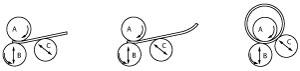
Initial Pinch, Three Roll
One of the most common plate rolling configurations, the initial-pinch system entails introducing the plate to the rolls so that roll A and B grip the part, while roll C performs the first prebend. Next, you turn the material 180 degrees and insert the plate to prebend the other edge. Then, you use all three rolls to close the cylinder.
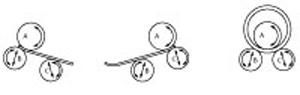
Double Pinch, Three Roll
In this setup, you first lower roll C and raise roll B, then introduce the plate between A and B. Once the plate is gripped, you raise roll C to form the first prebend. Next, you pass the roll through the machine so that the plate is gripped between rolls A and C, then raise roll B to perform the second prebend. Finally, you position the rolls in a standard pyramid configuration and roll the cylinder.
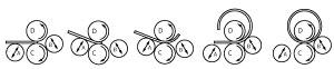
Double Pinch, Variable Geometry
Unlike any other plate roll type, the variable-geometry variety offers a top roll that is not fixed, but instead moves up and down. In this arrangement, you introduce the plate, and then move rolls B and C horizontally so that roll B is almost directly under roll A. You bring roll A down to form the first prebend on one plate edge, then feed the plate through and move the bottom rolls horizontally so that now roll C is almost completely under roll A. Roll A descends to perform the second prebend. Finally, you position the rolls in a standard pyramid to roll the cylinder.
Double Pinch, Four Roll
These machines are known for their speed, mainly because the workpiece doesn’t have to be removed before rolling to perform the second prebend. You introduce the plate, and the machine grips it between rolls D and C. Roll A then moves up for the first prebend. The system then forms the cylinder, after which roll B raises up to perform the second prebend.
Urethane, Two Roll
These rolls tend to work well in high-volume environments with thin-sheet applications, usually 3⁄16 in. and less. In this setup, a mandrel (also called a spindle pipe) mounted on roll A determines the cylinder radius, so if you need to roll a different radius, you need to change out the mandrel. Once set up, though, operation is simple. You raise roll B against roll A, square the plate against the two rolls, and then execute the rotation.
Content courtesy of Faccin USA Inc., 907 S. U.S. Highway 301, Tampa, FL 33619, 813-664-8884, www.platerolls.com.


The Fabricator is North America's leading magazine for the metal forming and fabricating industry. The magazine delivers the news, technical articles, and case histories that enable fabricators to do their jobs more efficiently. The Fabricator has served the industry since 1970.
start your free subscription
Easily access valuable industry resources now with full access to the digital edition of The Fabricator.

Easily access valuable industry resources now with full access to the digital edition of The Welder.

Easily access valuable industry resources now with full access to the digital edition of The Tube and Pipe Journal.

Easily access valuable industry resources now with full access to the digital edition of The Fabricator en Español.
In this episode of The Fabricator Podcast, Caleb Chamberlain, co-founder and CEO of OSH Cut, discusses his company’s...


