


Contributing Writer
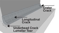
Figure 1: Crater cracks occur when the weld pool does not have enough volume after cooling to overcome shrinkage stresses.
One of the primary objectives of any weld fabrication is to prevent weld defects, especially cracks. Cracks are the most severe of all weld defects and are unacceptable in most circumstances. Rework robs the company of precious time and material (that is, money), so prevention is the primary concern.
Cracks don’t always happen immediately after welding, and certain cracks, such as the underbead variety, may not be open to the weld surface. Cracks can develop over time after the weld has been subjected to loads while in service. Tensile and fatigue loads; bending, twisting, or flexing; as well as hot and cold expansion and contraction all can occur long after welding, be it two days, two months, or even two years.
The major cause of a crack is when internal stresses exceed the strength of the weld metal, the base metal, or both. And once a focal point for these stresses—that is, a stress riser—develops and accumulates, a crack can propagate.
A discontinuity is a weld fault that may or may not be serious enough to cause a rejection. Whether or not it violates code specifications will depend on further examination by a competent person against code requirements or in-house quality assurance specifications. If the fault violates either of these two, it becomes a defect. Defects require repair, but discontinuities do not. Violations of customer requirements often fall under the discontinuity rule and the weld will have to be repaired.
In short, defects always are discontinuities, but not all discontinuities are defects.
The responsibilities of both welder and supervisor affect weld quality. The welder is responsible for the defect when it is due to his or her skill level or weld deposition technique. Weld characteristics like incomplete fusion, excessively concave or convex bead contours, and improper weld size all can come from poor welding technique, improper travel speed, poor electrode manipulation, incorrect weld parameter settings, as well as failure to notify supervision of a problem with the job at hand.
Supervisors must ensure welders have the tools necessary to do an effective job. They must maintain a shop safety program in compliance with OSHA regulations. They also should, among other things, ensure welders are using the correct base and filler metal; have proper weld procedure testing; work with adequate and functional welding equipment; receive effective and meaningful welder training; and work with properly designed, accessible weld joints.
Responsibility often goes beyond the welder and supervisor, especially when design-for-manufacturability issues come into play. For instance, joint accessibility has become more of a problem nowadays as many designers are not adequately familiar with the requirements of depositing a serviceable, defect-free weld. Can the welder get the gas metal arc welding gun, shielded metal arc welding electrode, or gas tungsten arc welding torch to the work area and still see the joint—or is he welding blind? Does the welder have enough room to manipulate the electrode at all the required angles to deposit a good weld, and still see the joint?
If no design alternative exists, managers must plan for potential weld errors. If an unacceptable weld defect occurs, can a worker get a grinder into the joint to remove the bad weld? If so, how will the weld be repaired? A welder or supervisor can answer all these questions, but the best solution often requires input from customers and product designers.
The weld pool has a tremendous amount of built-in stress from weld metal contraction, or shrinkage. Liquid metal is at its maximum expansion, or volume, and so when it cools and solidifies, it has only one direction to go. If the weld pool does not have enough volume after cooling to overcome shrinkage stresses, a crater crack will form, often near the end of a weld, in a high-stress, low-strength area (see Figure 1). It’s the weld’s way of relieving stress.
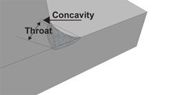
Figure 2: An excessively concave weld bead contour is a serious candidate for centerline cracking.
The length of the weld deposit also is highly stressed, so that crater crack can very easily travel back through the entire length of the weld centerline. This is a common problem in aluminum and some tool and die steels. The remedy is simple: Fill the crater to its full cross section (the same as the weld size) before the weld is finished. You can accomplish this with various methods. You may pause for two or three seconds at the end of the weld before stopping the arc; or you may choose to backstep (reverse direction of travel) for about 0.5 inch at the end of the bead.
An excessively concave bead profile is a common problem with fillet welds, especially those on stainless steel, INCONEL® alloys, and aluminum, but plain carbon steel isn’t immune. A certain amount of concavity may be acceptable, depending on the welding requirements. But an excessively concave weld bead contour (see Figure 2) is a serious candidate for centerline cracking. It generally occurs immediately when welding aluminum (where it’s often called “hot cracking”), and is slightly delayed in other materials, after the metal cools to about room temperature.
The problem with concave welds is very similar to that with crater cracks. Reducing the weld throat reduces its strength dramatically, because there isn’t enough filler metal in the weld cross section to combat shrinkage stresses. This means those stresses are in control, and a crack develops. If the weld has insufficient throat depth, it probably has insufficient strength.
As with crater cracks, preventing such centerline cracking isn’t difficult. Two principal culprits are incorrect travel speed and voltage setting. Voltage is a measure of electrical “pressure,” a force pushing down on the face of the liquid weld metal. A small reduction in arc voltage (1 to 1.5 volts) can make a big difference in the weld bead’s contour. Reducing the voltage too much, though, can result in a severely convex weld bead contour. (Note that pulse GMAW brings up further considerations that are beyond the scope of this article.)
If you set voltage too high, the weld pool becomes difficult to control, and this may encourage you to increase travel speed. This in turn gives you insufficient weld throat depth and weld strength. Once the pool gets ahead of the arc, it’s over. You probably will get incomplete penetration, lack of fusion, and undercutting—common problems with vertical-down welding. In fact, performing a vertical-down fillet weld with an acceptable weld throat requires masterful weld pool control. To avoid these problems, slow the travel speed and give the weld time to build an acceptable bead contour.
Excessively convex bead contours—that is, excessive weld reinforcement—isn’t generally associated with weld cracking, though such welds can cause problems. You can waste a lot of time and weld metal depositing an excessively high bead profile. Such a weld is unsightly and almost always unacceptable, mainly because of the weld re-entrant angle to the base metal (see Figure 3).
Such bead shapes can have an effect on cracking, especially on cracking that occurs over time. The crack generally is directed down into the base metal, right at the weld toe. If you don’t create a smooth transition of weld metal to base metal, you can disrupt the flow of forces through the weld. Such a high volume of weld metal creates significant shrinkage forces. When these forces exceed the strength of the weld, cracking ensues.
To avoid this problem, try increasing travel speed. You can also take a look at your voltage setting. A small increase in voltage increases electrical pressure, forcing the weld contour down to a more acceptable profile.
Undercut defects (see Figure 4) reduce the base metal thickness where the base metal meets the filler metal. This loss of metal interrupts the transfer of stresses from member to member through the weld. If severe, this creates a stress concentration point and has the potential to accumulate and initiate a crack, rapidly.
On high-stress joints, acceptable levels of undercut are near zero. The American Welding Society’s D1.1, D1.2, D1.5, and D1.6 codes have extremely low acceptable limits of undercut, depending on the defect’s orientation in relationship to the applied stress direction and base metal thickness.
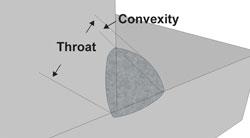
Figure 3: Excessively convex weld bead shapes can have an effect on cracking, especially on cracking that occurs over time.
Undercut develops because of improper welding techniques and procedure settings. It usually has no single cause but can come from a range of factors, including incorrect voltage settings, travel speed, and electrode-to-work angle. On fillet welds especially, if voltage (electrical pressure) is too high and the electrode angle favors one member more than another, the arc force will “wash away” the favored member at the weld toe. If the electrode favors one member more and the travel speed is too fast, the arc will naturally melt the member as part of the fusion process, but the high travel speed will not allow the melting electrode to fill in the washed-out area, resulting in an unacceptable weld.
To prevent these defects, make every effort to maintain proper voltage levels. For the constant-voltage processes (nonpulsed GMAW and flux-cored arc welding), the voltage stays fairly constant and can be adjusted manually. For constant-current processes, GTAW, and SMAW, voltage varies with the arc length. If you increase the arc length, you increase arc voltage. Be sure to maintain a correct electrode angle, and try decreasing travel speeds to allow weld deposition to do its job.
Overlap (see Figure 4), or cold lap, is more serious than you might think. If the weld toe remains cold enough that it doesn’t fuse with the base metal, the weld just laps over, or lays over the base metal surface without fusing. This leaves no continuity between the weld metal and base metal, so there isn’t a path for stress to transfer through the weld into the adjoining member. A classic example of a stress riser, such overlap opens the door for cracking if stress accumulates to unacceptable levels.
Again, the fix isn’t difficult. If you don’t work the electrode evenly between the two base metals, the weld will favor one member more than the other, and the working parameters (amps and volts) will not liquefy the base metal evenly. Overlap is a common fault when you have to weld blind. Obviously, having to guess where the joint is won’t produce favorable results.
The AWS codes call for a “smooth transition” at the toe of the weld. This ensures that the weld stresses flow evenly and, most important, stops those detrimental cracks from forming.
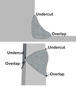
Figure 4: Undercut defects reduce the base metal thickness where the base metal meets the filler metal. Overlap, or cold lapping, occurs when the weld toe remains cold enough that it doesn’t fuse with the base metal, but instead just laps over, or lays over, the base metal surface.

The Fabricator is North America's leading magazine for the metal forming and fabricating industry. The magazine delivers the news, technical articles, and case histories that enable fabricators to do their jobs more efficiently. The Fabricator has served the industry since 1970.
start your free subscription
Easily access valuable industry resources now with full access to the digital edition of The Fabricator.

Easily access valuable industry resources now with full access to the digital edition of The Welder.

Easily access valuable industry resources now with full access to the digital edition of The Tube and Pipe Journal.

Easily access valuable industry resources now with full access to the digital edition of The Fabricator en Español.
In this episode of The Fabricator Podcast, Caleb Chamberlain, co-founder and CEO of OSH Cut, discusses his company’s...


